KEMEJA LENGAN PANJANG

HARGA : Rp.80.000 UKURAN : ALL SIZE (M) KODE BAJU : KLP (untuk lengan panjang ) hubungi : 085718231737

KEMEJA LENGAN PENDEK

HARGA : Rp.80.000 UKURAN : ALL SIZE (M) KODE BAJU : KMP (untuk lengan pendek ) hubungi : 085718231737

KEMEJA TOPI

HARGA : Rp.90000 UKURAN : ALL SIZE (M) KODE BAJU : KMT (untuk TOPI ) hubungi : 085718231737

JAKET BERMOTIF SALJU

HARGA : Rp.80000 UKURAN : ALL SIZE (M) KODE BAJU :JKM (untuk merah ) hubungi : 085718231737

bantu di vote ya

Wednesday, April 12, 2006

Object Styles Explained

Object styles are located both in the project and in families. Every family, system and annotation category has atleast one object style. They are used to control globally how an object is displayed with regards to lineweight, colour and type. These can be overridden per view or changed throughout a project either in your "visibility graphics controls" or your "settings->Object Styles" respectively.

In a family:

When you are in a family going to settings->Object Styles can create new subcategories for elements that will enable them to be turned off or their display manipulated without changing all elements in that category. For example:

Say we have a generic model family and we create a new object style by going to our object style settings, clicking NEW and selecting sub-category of generic models and name in "Signage". We could then select individual solid geometries located in our family and go to their properties and set their subcategory to "Signage". Now if we were to load this family into a project we could turn off signage in our visibility settings and it would just turn off these geometries whilst keeping on our other generic models.

The other items that are created when adding a new object style are new linetypes (this is where some people become confused as in families you do not create new linetypes you create new object styles). If we were to select symbolic lines in our family you'll note that two new linestyles are now selectable. That is, Signage (cut) and Signage (projection). Similarly lines drawn in this object style can be turned off or manipulated independant of all generic models as previously outlined.

In a project:

In Settings->Object Styles in a project we can change how a particular sub-category or category is displayed globally throughout the model by editing its properties. You'll note we have multiple tabs, for model, annotation etc for the different classes of elements.

These can also be overridden per view to enable exceptions to the graphical display of these elements for paricular views.

Nested Arrays & Formulas

I have recently updated my tutorial for nested arrays and formulas which was getting quite old. The tutorial is available here: Nested Families & Arrays

Just in summarisation though, best practices when creating parametric arrays:

1. Always use nested families for elements that are to be arrayed

2. Always constrain the two defining elements of the array in all 3 axis. (defining elements are either the first and second or first and last depending on which option you've selected when creating your array)

3. Always constrain your arrayed elements by dimensioning to their origins. (their origin is the intersection of the three "defines origin" reference planes - THIS SHOULD BE LOCATED AT A LOGICAL POINT THAT YOU WANT TO CONSTRAIN TO, TO AVOID EXCESSIVE DIMENSIONS AND PARAMETERS)

Hopefully this quick cheat sheet can be used to diagnose issues with malfunctioning arrays.

Saturday, April 8, 2006

Making "Elevation" tags look like Section Heads (pre-Revit 2011)

Okay, so we can't yet make elevations look the way we want them to. This is my typical workaround that i use in my office where the elevation appearance is critical (functionally you are still better using the elevations).

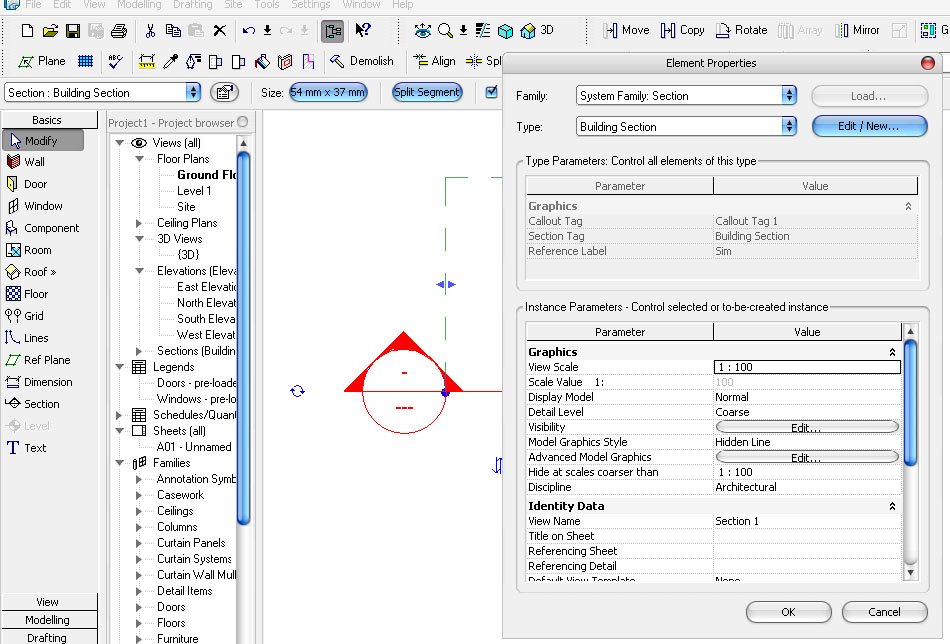
Begin with a standard section:


Now select it and go to its properties and choose Edit/New:


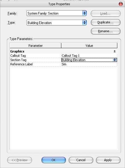
Now we want to duplicate this section type and call it "Building Elevation" for example:


Now if we Okay out of each of these windows and goto our Settings-->View Tags-->Section Tags... Settings, we can create a new section tag type called Building Elevation and set it to have Section Tail = none:


Now we need to select our section and go to its properties and tell it to use this new section tag type that we have created:


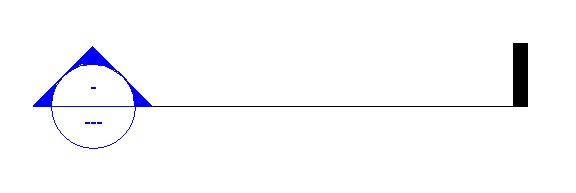
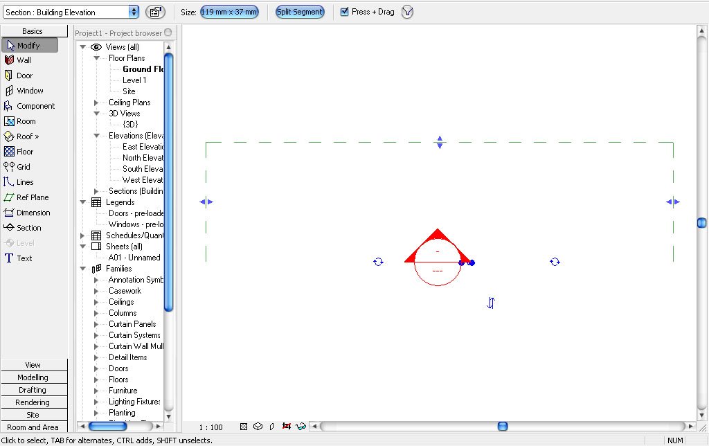
We should now have a section that uses the Section-Building Elevation type and it doesn't have a tail:


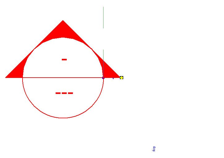
Now if we select this section again, and drag the section line end point back to the head, MAKING SURE TO LEAVE A SMALL EXTENSION PAST THE HEAD (otherwise we'll have difficulty actually using the section/moving it etc):


Finally its just a simple matter of adjust the sections crop regions so the head is roughly centred. Now we have a section tag that looks like an elevation marker and still has much of the same functionality. However it now looks how we want it to and all information (detail number/sheet number etc) are displayed within the actual marker, unlike elevation tags.

Personal Wishlist - Updated for RAC2008

There are many wishlists around but unfortunately none of them capture all that I'd like to see added/improved so I thought I'd post them. I believe it will also be a good reference for new users to see what isn't currently possible (without workarounds)... Note: some of these have been taken from the AUGI wishlist forums.

1. Elevation Tags
We need to be able to further customise these tags to achieve the standards we require. Whether this be by making them external families ala sections tags or simply allowing more options to customise their display.

2. Filtering of Sections by type (Now possible to an extent with the 2008 Hide in View tool)
How many of us spend countless hours using hide annotation in view to hide unwanted sections in a view. It would be great if we could filter the sections per view based on their type!

3. View Depth Clipping of Lineweights in section and elevation!
Sections/Elevations often look flat and are difficult to read, this needs to be implemented. Workarounds such as turning on shadows greatly increase printing time to an unacceptable amount.

4. Adding a new family category for SIGNAGE that has a setting that enables you to stop the signage from flipping when mirrored.
This would be great for mirroring projects.

5. Improved Site Modelling tools (Slightly improved in 2008 with the floor point edit tool)
Currently modelling things like kerbs that follow topography or having components located underground that display correctly in section (with earth hatch wrapping around them) are somewhat difficult to achieve.

DELETED 6. Improved handling of Groups (No longer an issue in 2008)
Groups can be somewhat unreliable with changes to a group often resulting in being unable to "finish group" and then having to ungroup and regroup certain items. Things like this need to be addressed.

7. Addition of further modelling tools (improved in 2008 with point edits...)
The ability to import SAT is great but it would be better not having to purchase another program in order to create complex NURB forms easily.

DELETED 8. The ability to have semi-transparent filled regions (available in 2008)
Sometimes there is the need to lightly hatch over an area without either fully blocking it out or making it too visible.

9. Ability to add views when working in an in-place family
All too often do we need to quit the family and setup some views in order to achieve what we're after...

9. A quick paintbrush tool for resequencing numbering of doors/windows/carparking etc when a change is made.
It's quite time consuming when a change occurs at door 2 and there are three hundred odd doors to renumber. Also when placing anything that is tagged they should have automatic sequential numbering based on your first selection/tagging method (numbers/letters etc).

10. The ability to have lettered revisions as well as numbered
I'm sure most architectural office use both letters and numbers for different stages of the design process. This needs to be implemented in order to make the revision schedule a valid tool, as well as the next item.

11. Greater ability to customise the way schedules appear.
We need the ability to rotate schedules so the column headers can be on the side or the bottom of the schedule. Also the ability to flip the direction in which new rows are added. For instance, the field at the bottom is filled first and subsequent fields added above as required.

12. Greater control of wall layer visibility.
Sometimes we need to only show structural layers of a wall in a view as the finish layers overcomplicate the drawing. Workarounds are not sufficient for this.

13. NON-RECTANGULAR crop regions!
This is very common practice. Having to filled region or masking region (2008) out the unwanted information is annoying and time wasting.

14. Views between sheets need to be able to be aligned
Maybe an underlay sheet tool would be good for this so we can ensure the views appear in the exact same location.

15. Allow true colour representation of views (improved in 2008 with transparent filled regions)
Often light pastel colours will show as white meaning we must use bright ugly colours in order to get differentiation between areas...

16. Rescaling of hatch patterns without having to find the pat file
Its annoying having to find the pat file again and re-import it just to rescale a hatch pattern.

17. A select all instances per view tool
Select all instances is great but there are times when you only want to select from what is shown.

18. Improved DWG Export
Dimensions and text when exported need to create new text and dimension styles instead of using "standard" as this will vary between computers. Also the location of text in dimensions and the witness lines should link to the AutoCAD dimension style settings instead of using proxy overrides.

19. Additional Text control tools (MODEL & DRAFTING)
If we are to improve upon the days of ole (AutoCAD) we need all the text control options that were available there. For instance, the ability to create oblique text, adjust character spacing and adjust text width factor in model text as well.

20. The ability to have decals appear in a shaded view
Those of us who need to show signage, it would be great is we could place these in a way that they display in a standard shaded view without the need to render the view or insert a jpg and line it up...

21. The ability to attach walls to stairs and have stairs join to floors
Stairs are still fiddly and don't have all the flexibilies required. Multi-level stairs need to be able to attach to floors (monolithic). Walls should be able to attach to the underside. Spiral stairs should be able to go further than 360°. Spiral treads need to overlap.

22. Better control of hosted Railings
Railings on stairs when their heights are incorrect, we need the ability to manual edit the 3D path to ensure the railing follows the appropriate angles etc. Although this is sort of possible some slopes are still difficult to achieve. It would also be great if we could tab select the balusters and adjust them individually as an override as spacings are rarely the same...

Thursday, November 17, 2005

FREQUENTLY ASKED QUESTIONS

Frequently Asked Questions:

1. How can I override the dimension text? (You can now do so in R2009+)

Simple answer, you can’t. Workarounds are best explained here http://revitoped.blogspot.com/2005/11/de-value-engineering-dimensions.html

2. I created some levels but there aren’t any plans associated with them, can I add them?

Of course: Go to View->New->Floor Plan… and simple select the views you wish to create plans for. The standard windows ctrl and shift click selections apply here. The same principle applies for ceiling plans.

3. I can’t see some of my levels in one of my elevations/sections?

All levels/grids/sections (referred to as datums) have 3D and 2D extents. If the 3D extents of that level don’t cross the 3D extents of the section or the elevation they will not show. Therefore, to make them show you need to adjust them in an elevation/section so they do intersect. When you select a datum an indicator displays showing whether the datum is currently set to 3D or 2D extents. This is a toggle, click on it to toggle its value. If you right click on the datum in a view it does display in and select maximise 3D extents it will expand the extents to the full boundaries of your model, which should hopefully make it show up in your appropriate view.

If they don’t show in any views, you’ll need to create a scope box. Under your drafting tab is a tool called scope box, use it to draw a 3D box completely around the extents of your model. Now in elevation add another level (this will be temporary), right click and choose “select all instances” go to the properties and there is a category called extents. Where it says none, click and choose your scope box for the drop down menu. Then click okay and your levels should now appear as there extents have been adjusted to that of the scope box. You may delete the scope box now if you have no further need for it.

4. How do I place a door in a curtain wall?

Curtain walls do not behave the same as normal walls and doors are not placed in the same manner. There are two options for placing a door in curtain wall.
In your modelling tab, place curtain grids to break up the panel to the size you’d like to make your door. Switch to a 3D view, hover over the edge of your curtain wall panel where you’d like to place the door. Now use the key to cycle through the various options to select the panel you’d like to change to a door. Now in the element drop down menu where it says System Panel: Glazed, change the panel to the appropriate loaded curtain wall door family. That’s it, now just adjust your grids appropriately to get to the correct size and apply mullions as appropriate.
The other option is to change the panel to a wall type. You may have noticed in the previous method you could pick from available wall types. If you change the panel to a wall you are then able to place doors as you would a normal wall. You could even make the door take up the full extents of the wall so it wouldn’t matter what wall type you actually used. There are issues currently with this method and schedule to and from room information of doors placed this way.

5. Can Revit create linetypes with text along the line or symbols to represent stormwater or various other services?

The short answer is no. You can create a line based detail component, but the text symbols would need to be a nested symbol family. I've created one which enables me to set the value for the text to anything I want as a Type parameter. You can't currently do this for a curved line though...

6. How do I change the swing angle in plan of my doors?

This feature is only available if the door has been created with an instance parameter for the adjustable swing. This is best explained in the in-built Revit Tutorials.

7. How do I create my own hatch patterns?

You can either learn the appropriate code to edit the pat files directly using a text editor such as notepad or utilise a program such as Hatchkit. http://www.hatchkit.com/

8. How do I change a model pattern to a drafting pattern or vice versa?

Edit the PAT file using notepad and add or change the following values:
;%TYPE=MODEL for model or
;%TYPE=DRAFTING for drafting.

You can also set the units with the following operator:
;%UNITS=MM to set to millimetres…

9. How do I change the elevation symbols to match my section markers? (You can now do so in R2011+)

This isn’t possible. Elevation tags are system families and can only be modified using the settings in the elevation tag properties… This is a long standing wishlist item.

My typically workaround (for times where its absolutely necessary that the elevations look a certain way) is to create a new section type called "Building Elevations" Then I'll give the section a head with no tail, then drag the section cut line in plan to be short enough that its not visible. Refer to the tutorial...

10. I have a window above the cut plane that I need to display but I can’t change the cut plane without effecting everything else?

Create a plan region. A plan region allows you to draw a boundary and adjust the view range settings for that area independent of the rest of the view. The great thing about 2008 is no longer do you have to search for plan regions by hovering around your model, they now display a boundary in plan that doesn't print.

11. How do I apply different materials to individual wall faces or similar without having to make a new type?

Use the paint brush tool from the tool bar. Select the appropriate material then pick the face you’d wish to paint; to reset the material back to its original settings, paint it with the by category material.

12. How do I attach a wall to the underside of a stair/ramp?

Refer to this tutorial. http://www.revitcity.com/tutorials/stair-wall_trimming/. Hopefully this process will become more automated with future releases. Another way is to use the ramp tool, or to select the wall and split it at each tread...

13. I placed a beam but I can’t get it to show in section/elevation (it only shows as a line)?

Change the detail level of the view from coarse to medium or fine.

14. How do I create a slanted/sloped column? (You can now do so in R2010+)

In 2010 onwards simply use a structural column and set the angle in its instance properties.  Otherwise, you need to create a column with adjustable parameters for the angle. Refer to this thread: http://www.revitcity.com/forums.php?action=viewthread&thread_id=592#2062

15. The floor hatch pattern is showing through my plumbing fixtures/furniture in my plans, how do i stop this?

This is caused by a setting in each of the families themselves. If you edit the family, switch to a 3D view and select all the 3D geometry, then hit the visibility button on your top tool bar. You'll notice that its turned off in plan, you can turn it back on here and reload if you like.

If the 3D geometry is an imported dwg, there maybe excessive 3D linework which you don't want to display in plan. In this case you'll need to create a masking region (2008) to represent the element in plan and line up with the 3D geometry - you'll also most likely need to do this in front and side elevations as well.

16. How do I create a canted/slanted/tilted/angled wall?

You need to create a mass to give you the correct angled surface of which to place your slanted wall. Masses are used as an invisible framework to control entire building layouts or complex geometry such as this.

Once you have created your mass, either by solid extrusion or a blend (depending on the slanted walls complexity), you can use the Wall->By Face option or Curtain System by face for curtain walls. Just select the type of wall you'd like to place then pick the surface.

Then its just a matter of turning your mass visibility off...

You can use geometry created in other programs as a mass (such as sketch up or Rhino)

17. How do i save back to a previous version of Revit?

This is not possible. Revit is bought on a subscription basis only, so there is never a reason not to have the latest version installed. This way the Revit support team can concentrate on supporting one version of Revit rather than having to maintain superseded releases.

18. Red Question marks are showing up in my titleblock and i can't type in the appropriate values?

This means that there are shared parameters in your titleblock which are yet to be loaded into your project. If you are not aware of what shared parameters file they are located in and the parameters names, edit the titleblock, select the label and edit the parameter to find out where its located first.

Then in your project goto Setting-->Project Parameters-->Add-->select shared parameter and navigate and find the parameter you wish to add-->Select what category of families you wish the parameter to apply to, in this case either project info or drawings sheets (generally drawing sheets)-->Then select whether its an instance parameter or a type parameter-->Hit Okay and repeat for any additional parameters.

19. When rendering there is this plane showing through my building that i can't get rid of?

This is most likely a ground plane. Many people forget that the ground plane is set in TWO locations and must be off in both of them.

These locations are:
Settings-->Render Scene-->Environment-->Advanced... Ground plane
and
Settings-->Sun & Shadow Settings-->Ground Plane at level.

Turning this off in both this locations should resolve the issue.


20. Why won't my family show cut by a section?


If you look in your Visibility Settings (shortcut - VG or VV) you'll see in the Cut column some cells are greyed out. This particular family categories do not show cut by a section. Instead if a family is cut of this category the entire family displays. This was obviously implementing for items such as a couch where you don't want to see if being cut in a section. Personally I think all families should have the option in their settings as to whether they are cut or not rather than not giving us a choice.


To resolve this go to Settings-->Family Category & Parameters and change your family to a category that will show cut.